Questions can be sent to: [email protected]

Overview

If you have started looking through our MATLAB and Python demos, you will probably have encountered code that looks like this:

Datapixx('RegWrRd');
DPxUpdateRegCache()
device.updateRegCache()

And possibly this:

Datapixx('StopAllSchedules');
DPxStopAllScheds()
device.din.stopSchedule()

If you’re curious about what these commands do, this guide is for you.

Registers and schedules are core mechanics of VPixx Technologies’ microsecond-precision synchronization systems. Along with a centralized clock, they allow us to record and align the timing of stimulus presentation, outgoing triggers and incoming signals.

While you can program your experiment without fully understanding these concepts, we find that knowing how they work helps you write more efficient code and take full advantage of the synchronization abilities of your devices.

In this guide we will cover both registers and schedules. We will address how and when they are used by your VPixx device, and how to write to and read from them. We will give examples and identify functions in both MATLAB and Python.

This guide applies to any VPixx hardware with support for MATLAB and Python APIs (APIs available for download here). This includes the DATAPixx video I/O hub, the PROPixx controller, the VIEWPixx and VIEWPixx /3D, and the TRACKPixx eye trackers.

Notably, this guide does not apply to the VIEWPixx /EEG, as it does not use our MATLAB and Python libraries.

Registers

All API-supported VPixx devices have onboard system settings. The settings include information about the current state and operation of the device. Collectively, these settings are saved in what we call the device register.

A copy of these settings is saved on your experiment computer as well. We call this copy the local register.

DATAPixxSchematic
An example schematic of a DATAPixx3 setup with audio and a response box. Here, the device register is the DATAPixx3

When we write a line of MATLAB or Python code that tells our VPixx device to do something, we are changing the contents of the local register. In other words, we are changing the copy of the device settings stored on our computer. With a few exceptions (see the blue Tip box below), this code will not automatically alter the state of the device register.

In order to update our device register with the changes we have made to the local register, we need to perform a register write.

Say we want to turn on Pixel Mode, a mode which automatically sends out digital TTL triggers based on the colour of the top leftmost pixel on the display. In MATLAB, we can do this with the command:


MATLAB/Psychtoolbox

Datapixx('Open');

Datapixx('EnablePixelMode'); fprintf('Nothing happened?'); Datapixx('RegWr'); fprintf('Pixel Mode is active!');

Python (libdpx wrapper)

from pypixxlib import _libdpx as dp

dp.DPxOpen() dp.DPxEnableDoutPixelMode() print('Nothing happened?') dp.DPxWriteRegCache() print('Pixel Mode is active!')

Python (object-oriented)

from pypixxlib.viewpixx import VIEWPixx
vp = VIEWPixx()
vp.open()
vp.dout.enablePixelMode() print('Nothing happened?') vp.writeRegisterCache() print('Pixel Mode is active!')

The command ‘EnablePixelMode’ did indeed do something—it changed the state of the local register. In order for the VPixx device to actually initiate Pixel Mode, this mode has to be enabled on the device register as well. So, we push our command to the device using ‘RegWr’, and then Pixel Mode is enabled.

A summary of register writing. Register writes are one-way, and should be used in situations where the user wants to execute changes quickly, and does not need feedback from the hardware.

Almost all of our functions for MATLAB and Python require a register write in order for them to be implemented on your VPixx device. There are a handful of special functions (like ‘Open’ and ‘Close’) which are automatically passed to the device register. These functions don’t need to be followed by a register write.

A major advantage to register writing is that it allows several tasks to be executed simultaneously. Simply write multiple commands to the local register, and execute a single register write to enable all changes on the device register at the same time.

For example, say we want to start eye tracking and send a digital TTL trigger simultaneously:


MATLAB/Psychtoolbox

%First, let’s set up an eye tracking schedule. We’ll cover schedules in more detail in a bit. For
%now, we will say we are preparing the recording without starting it.
Datapixx('SetupTPxSchedule');
%We pass this to the device register so it is ready to go when we want to start recording
Datapixx('RegWr');
%Next, we tell the local register to start eye tracking. Recording won’t start until the next
%register write when the command is passed to the device:
Datapixx('StartTPxSchedule');
%Now let’s define our digital trigger. We will set DOut 0-3 to high, and everything else to low.
doutValue = bin2dec('0000 0000 0000 0000 0000 1111');
Datapixx('SetDoutValues', doutValue); 
%Nothing has happened yet! Let’s initiate both the digital trigger and start recording
%simultaneously, by updating the device register with our recent changes:
Datapixx('RegWr');

Python (libdpx wrapper)

Coming soon

Python (object-oriented)

Coming soon

Another advantage to using registers is that you can wait for a specific event to perform the write. Any new states or commands written in the local register will be pushed to and implemented on the device register when this event occurs. This allows us to synchronize our experiment I/O with properties of the video signal. Below is a list of currently supported register write commands:

Perform a register write immediately
MATLAB/PsychtoolboxDatapixx(‘RegWr’)
Python (libdpx wrapper)DPxWriteRegCache()
Python (object-oriented)device.writeRegisterCache()
Perform a register write on next vertical sync pulse/start of the next frame
MATLAB/PsychtoolboxDatapixx(‘RegWrVideoSync’)
Python (libdpx wrapper)DPxWriteRegCacheAfterVideoSync()
Python (object-oriented)device.writeRegCacheAfterVideoSync()
Perform a register write on next instance of custom sequence of pixels
MATLAB/PsychtoolboxDatapixx(‘RegWrPixelSync’)
Python (libdpx wrapper)DPxWriteRegCacheAfterPixelSync()
Python (object-oriented)device.writeRegCacheAfterPixelSync()

Our Python tools come in two flavours, which reflect two distinct programming styles:

The libdpx wrapper is procedural, and prefaces all functions with “DPx.”

Our object-oriented programming tools require users to first define a VPixx device object, and then call its functions and attributes. Specific functionalities are stored in subclasses, such as AnalogIn and DigitalOut.

Say we want to send out a digital TTL trigger when our specific visual stimulus occurs. In the top left corner of the video frame containing the stimulus, we draw a sequence of 8 alternating red and green pixels. Then, we use a register write command which waits for this sequence of pixels to send the command to fire a TTL trigger to our device register.


MATLAB/Psychtoolbox

Datapixx('Open')
%First, we define the pixel sequence we are waiting for. In this case, it is a series of 8 red and
%green pixels in the top corner of our image. We define these pixels in a 3 x 8 array, where the
%columns are the number of pixels in the sequence and rows are the red, green and blue values of the
%pixels.
pixelTrigger = [255, 0, 255, 0, 255, 0, 255, 0;    %R
                  0, 255, 0, 255, 0, 255, 0, 255;  %G
                  0, 0, 0, 0, 0, 0, 0, 0];         %B
%Next, we set our desired digital output. Let’s say we want to set DOut 4-7 to high, and everything
%else to low. This command is stored in the local register for now.
doutValue = bin2dec('0000 0000 0000 0000 1111 0000');
Datapixx('SetDoutValues', doutValue);
%Nothing has happened on the device register yet. Let’s write an update to the device register on
%the next appearance of our pixel sequence, i.e., when our target appears.
Datapixx('RegWrPixelSync', pixelTrigger);


Python (libdpx wrapper)

from pypixxlib import _libdpx as dp
import numpy as np
dp.DPxOpen()
#First, we define the pixel sequence we are waiting for, the pixeTrigger. In this case, our 
#trigger is a series of 8 red and green pixels in the top corner of our image. 
#In Python, the pixel trigger RGB values are passed as a single vector, ie [R1, G1, B1, R2, G2, B2, etc]. 
#We use the numpy 'tile' function #to repeat our [red, green] pattern four times to generate the full trigger.
pixelPattern = [255, 0, 0, 0, 255, 0] #1 red and 1 green pixel
pixelTrigger = list(np.tile(pixelPattern,4))
#Next, we set our desired digital output. Let’s say we want to set DOut 4-7 to high, and everything else 
#to low. This command is stored in the local register for now. We use binary to represent all 24 digital 
#outputs and set positions 4-7 to 1. The int() command converts this value to one that can be read by the 
#device. 
doutValue = int('000000000000000011110000', 2)
bitMask = 0xffffff
dp.DPxSetDoutValue(doutValue, bitMask)
#Nothing has happened on the device register yet. Let’s write an update to the device register on 
#the next appearance of our pixel sequence, i.e., when our target appears.
timeout = 60 #seconds
triggerLength = int((len(pixelTrigger)/3))
dp.DPxWriteRegCacheAfterPixelSync(triggerLength, pixelTrigger, timeout)


Python (object-oriented)

import numpy as np
from pypixxlib.propixx import PROPixxCTRL
ppc = PROPixxCTRL()
ppc.open()
#First, we define the pixel sequence we are waiting for, the pixeTrigger. In this case, our 
#trigger is a series of 8 red and green pixels in the top corner of our image. 
#In Python, the pixel trigger RGB values are passed as a single vector, ie [R1, G1, B1, R2, G2, B2, etc]. 
#We use the numpy 'tile' function #to repeat our [red, green] pattern four times to generate the full trigger.
pixelPattern = [255, 0, 0, 0, 255, 0] #1 red and 1 green pixel
pixelTrigger = list(np.tile(pixelPattern,4))
#Next, we set our desired digital output. Let’s say we want to set DOut 4-7 to high, and everything else 
#to low. This command is stored in the local register for now. We use binary to represent all 24 digital 
#outputs and set positions 4-7 to 1. The int() command converts this value to one that can be read by the 
#device. 
doutValue = int('000000000000000011110000', 2)
bitMask = 0xffffff
ppc.dout.setBitValue(doutValue, bitMask)
#Nothing has happened on the device register yet. Let’s write an update to the device register on 
#the next appearance of our pixel sequence, i.e., when our target appears.
timeout = 60 #seconds
triggerLength = int((len(pixelTrigger)/3))
ppc.writeRegCacheAfterPixelSync(triggerLength, pixelTrigger, timeout)

We recommend a trigger sequence of at least 8 pixels when using PixelSync, to ensure the trigger is unique. To align the trigger with stimulus onset, the pixels should be embedded in the top of your stimuli, without any blending or dithering applied.

The power of registers becomes obvious as you add more and more simultaneous tasks. If, along with your digital output, you also want to:

  • play a tone
  • record audio
  • start analog output of eye position
  • listen for a button press

You can simply add these tasks to the local register and push them all to the device on that single RegWrPixelSync. All tasks will be initiated when your stimulus occurs in the video signal as it is read by your VPixx device.

Reading the device register

We have covered some examples of when you might want to update the device register with the contents of the local register. There are some cases in which we might want to do the opposite, and update the local register with whatever is stored on the device.

For example, if the device is recording data, we may want to know how much new data has been recorded since we last checked. We also may want to information about the device status, or the timestamp of a certain event. All of this information is stored on the device register. In order to update our local register with this information, we need to perform a register read.

To perform a register read, we first have to write the read request to our local register and pass it to the device register. The device then sends back a copy of its register, which is used to update the local register. Rather than doing this procedure in two lines of code, we have a set of write-read commands which perform a register write immediately followed by a register read.  In our Python library, this operation is often called a register update.

Perform a register write-read immediately
MATLAB/PsychtoolboxDatapixx(‘RegWrRd’)
Python (libdpx wrapper)DPxUpdateRegCache()
Python (object-oriented)device.updateRegisterCache()
Perform a register write-read on next vertical sync pulse/start of the next frame
MATLAB/PsychtoolboxDatapixx(‘RegWrRdVideoSync’)
Python (libdpx wrapper)DPxUpdateRegCacheAfterVideoSync()
Python (object-oriented)device.updateRegCacheAfterVideoSync()
Perform a register write-read on next instance of custom sequence of pixels
MATLAB/PsychtoolboxDatapixx(‘RegWrRdPixelSync’)
Python (libdpx wrapper)DPxUpdateRegCacheAfterPixelSync()
Python (object-oriented)device.updateRegCacheAfterPixelSync()
A summary of register updating, also known as a write-read. Register updates are round-trip transactions, and should be used whenever a copy of hardware status is needed. Register updates take longer than register writes, and are blocking functions.

It’s important to keep in mind that register write-reads are blocking functions. That is, everything else in your script is put on hold until the read is performed. Other blocking functions include Psychtoolbox’s screen flip and listening functions like KBWait(). This is something to be aware of when deciding between a register write, versus a register write-read. 

As an example, let’s look at sending out a trigger on a video frame containing our visual stimulus, which is a red circle.


MATLAB/Psychtoolbox

%Let’s open a black screen and draw our red circle
[windowPtr, ~] = Screen('OpenWindow', 2, [0,0,0]);
Screen('FillOval', windowPtr, [255,0,0], [500, 500, 600, 600]);
%Since our stimulus is a red circle on a black screen, let’s make our pixel trigger something
%obvious: a series of 8 red pixels. This marks the start of our stimulus.
pixelTrigger = [255, 255, 255, 255, 255, 255, 255, 255;    %R
                  0, 0, 0, 0, 0, 0, 0, 0;                  %G
                  0, 0, 0, 0, 0, 0, 0, 0];                 %B
%For our digital trigger, we’ll set all even DOuts to 1, and odd to 0.
doutValue = bin2dec('0101 0101 0101 0101 0101 0101');
Datapixx('SetDoutValues', doutValue); 
%Let’s set a write to update the device register on the next appearance of our sequence, and then
%show our image
Datapixx('RegWrPixelSync', pixelTrigger);
Screen('Flip');
%Wait for a keypress to continue
KBWait(); 

Python (libdpx wrapper)

Coming soon

Python (lobject-oriented)

Coming soon

Using a write-read here would cause a problem. Because the write-read is a blocking function, it would cause the code to wait for the pixel sequence to perform the register read before moving to the next line of our script. The next line is our screen flip, which contains our red pixel, which means we will be waiting forever.

On the other hand, using a register write will not create any issues, as it does not wait for a return value and so will not block subsequent code.

Using GetTime and markers for timekeeping

Your VPixx device has a central clock, which it uses for all recordings and timestamps. This makes it very easy to align multiple streams of inputs and outputs. The clock can be accessed by reading the device register.

Say we want to know the exact moment our device register was last updated. We can simply call ‘GetTime’, which returns the time, in seconds, between device power-up and the most recent register write-read.

For example, the following code will return a timestamp of when your audio schedule began.


MATLAB/Psychtoolbox

Datapixx('StartAudioSchedule');
Datapixx('RegWrRd');
audioStartTime = Datapixx('GetTime');

Python (libdpx wrapper)

Coming soon

Python (object-oriented)

Coming soon

As we have just seen, we don’t always want to perform a register write-read because it can block subsequent code while waiting for data from the device. In this case, we can create a “marker” to be used with a register write. This marker is stored in the device register and can be accessed with a write-read later on in your code.

Let’s expand on the example using our red circle stimulus. Say we want to know exactly when that first red pixel occurred and our digital trigger was sent out:


MATLAB/Psychtoolbox

[windowPtr, ~] = Screen('OpenWindow', 2, [0,0,0]);
Screen('FillOval', windowPtr, [255,0,0], [500, 500, 600, 600]);
pixelTrigger = [255, 255, 255, 255, 255, 255, 255, 255;    %R
                  0, 0, 0, 0, 0, 0, 0, 0;                  %G
                  0, 0, 0, 0, 0, 0, 0, 0];                 %B
doutValue = bin2dec('0101 0101 0101 0101 0101 0101');
Datapixx('SetDoutValues', doutValue); 
%Let’s create our marker here, before the write
Datapixx('SetMarker'); 
Datapixx('RegWrPixelSync', pixelTrigger);
Screen('Flip'); 
KBWait();
%Now let’s retrieve our timestamp
Datapixx('RegWrRd');
targetOnset = Datapixx('GetMarker');

Python (libdpx wrapper)

Coming soon

Python (object-oriented)

Coming soon

If we were to use ‘GetTime’ here, the returned timestamp would reflect the time of the register write-read following the keypress. Since ‘SetMarker’ was called prior to the write on pixel sync, ‘GetMarker’ will instead return the timestamp of that register write, which corresponds to our stimulus and trigger onsets.

Schedules

So far, we have discussed how to communicate between local and device registers to control the settings of our VPixx device. In this section we will turn to how we can use the onboard memory to store and record data.

This storage can be configured by defining buffers with a certain address and size. There are several types of buffers, that can be used for different types of data. Schedules are management functions which control the flow of information to/from each buffer.

For example, you might have one buffer that is logging participant button presses via the digital input, a second buffer which contains an audio file for playback during the experiment, and a third buffer that is that is recording eye tracking data. Each of these buffers has a unique address in the device memory:

Example memory allotment on a DATAPixx3

Below is a summary table of the types of schedules currently available with VPixx devices. For specific code syntax in MATLAB, enter ‘Datapixx’ in the command line for a full list of functions. In Python, you can search our online documentation here.

VPixx Buffer Types
Audio system
NamePlaybackRecordingDescription
Audio<align=”center”></align=”center”> Stores mono or stereo audio output
Microphone <align=”center”></align=”center”>Records audio on either MIC IN or Audio IN
Digital I/O
NamePlaybackRecordingDescription
Digital Input Log <align=”center”></align=”center”>Only records changes in the state of Digital IN (max 16 bits)
Digital Output<align=”center”></align=”center”> Stores TTL signals for playback on Digital OUT (max 24 bits)
Analog I/O
NamePlaybackRecordingDescription
Digital to Analog converter (DAC)<align=”center”></align=”center”> Stores content for playback on Analog OUT pins (+/- 10V)
Analog to Digital converter (ADC) <align=”center”></align=”center”>Records input from Analog IN pins (+/-10V)
Specialty systems
NamePlaybackRecordingDescription
PROPixx Tachistoscope<align=”center”></align=”center”> Saves individual images to a buffer and shows them on the display. Simulates a tachistoscope
TRACKPixx Eye Tracking <align=”center”></align=”center”>Records a 20-column array of eye tracking data, at a rate of 2000 samples per second

Not all schedules can be used with all VPixx devices. For example, the “Lite” versions of our products do not have the audio or analog buffer types. Similarly, the TRACKPixx eye tracking schedule is only available to researchers who have one of our eye trackers and a DATAPixx3.

While there are several kinds of data that may be stored in a buffer, the strategy for managing buffers is the same. Below are some general guidelines for creating and managing buffer X:

Setup

  • (Playback only) Write content to the buffer 
  • Set up a schedule to describe the type of data we expect the buffer to have, and other relevant parameters. If the buffer is going to be recording data rather than playing it, this is where the buffer address is specified
  • Write these changes to the device register to update the configuration of the device

Start recording/playback

  • Enter the command to start the schedule
  • Write this change to the device register to trigger start (optionally, you can synchronize it to video output using one of the special register commands)

Stop recording/playback

  • Enter command to stop the schedule
  • Write this change to the device register

Reading buffer contents

  • Perform a register write-read to get the current status of the device register
  • Get the schedule status, including number of new “frames ” of data in the buffer since the schedule started
  • Retrieve the desired number of frames from the buffer (note: the read buffer family of commands are a rare case of functions that do not require a register write or write-read; instead they execute immediately)

The functions for writing to buffers and setting up schedules often supply default memory addresses and sizes, so it isn’t necessary to set them yourself. However, if you are running multiple concurrent schedules it is always a good idea to double check you are not at risk of overlapping buffers, which will overwrite data.

Examples

In this section we will show some examples in MATLAB/Psychtoolbox and Python, showing how to implement different schedules. For more examples please refer to our demo libraries

Example 1. Play a beep 100 ms after visual stimulus onset

This example uses the audio buffer. Audio onset is triggered by pixel sync. The audio schedule is set up with an onset delay of 100 ms, so that the audio trails our visual stimulus onset by precisely that amount. We also use a marker to record the the time our visual stimulus appeared on screen. 


MATLAB/Psychtoolbox

%%
%SETUP
Datapixx('Open');
%Let’s define a 1 s, 500 Hz tone using Psychtoolbox’s MakeBeep and write it to a buffer at address
%16e6
duration = 1;
freq = 500;
[tone, samplingRate] = MakeBeep(freq, duration);
Datapixx('InitAudio')
Datapixx('SetAudioVolume', [0,0.5]);
bufferAddress = 16e6;
[~, ~, ~] = Datapixx('WriteAudioBuffer', tone, bufferAddress);
%Next we set up our audio schedule with a 100 ms delay start. Audio schedules also require a sampling
%rate for playback, which should match the sampling rate of our beep. We also set a buffer size 
%based on the length of our tone
bufferSize = duration*samplingRate;
onsetDelay = 0.1;
Datapixx('SetAudioSchedule', onsetDelay, samplingRate, bufferSize);
%We will use pixel sync to trigger playback. Let's define the pixel sequence which indicates the
%start of our stimuls: a green circle
pixelTrigger = [0, 0, 0, 0, 0, 0, 0, 0;                     %R
                  255, 255, 255, 255, 255, 255, 255, 255;   %G
                  0, 0, 0, 0, 0, 0, 0, 0];                  %B
%Configure settings on device
Datapixx('RegWrRd');
%%
%START
[windowPtr, ~] = Screen('OpenWindow', 2, [0,0,0]);
Screen('FillOval', windowPtr, [0,255,0], [500, 500, 600, 600]);
Datapixx('SetMarker'); 
Datapixx('StartAudioSchedule');
Datapixx('RegWrPixelSync', pixelTrigger);
Screen('Flip', windowPtr);
WaitSecs(1.1);
%%
%STOP
Datapixx('StopAudioSchedule');
Datapixx('RegWrRd');
stimulusStartTime = Datapixx('GetMarker');
Datapixx('Close');
Screen('Closeall');

Python (libdpx wrapper)

import numpy as np
from psychopy import core, visual
from pypixxlib import _libdpx as dp
#connect
dp.DPxOpen()
#Let's define a 1 s, 500 Hz tone via numpy array 
samplingRate = 44100
duration = 1
freq = 500
samples = np.linspace(0, duration, duration*samplingRate)
signal = np.sin(2 * np.pi * samples * freq)
#Convert this signal into a list of signed 16 bit integers that can be read by VPixx hardware 
signal *= 32767 /np.max(np.abs(signal))
signal= signal.astype(np.int16)
signal= list(signal)
#Initialize audio and set some basic parameters like volume and audio buffer address
dp.DPxInitAudCodec()
dp.DPxSetAudVolume(0.5)
baseAddress = int(16e6)  
bufferSize = len(signal)  
#Define this audio buffer on the device and write our signal to it 
dp.DPxSetAudBuff(baseAddress, bufferSize)
dp.DPxWriteRam(baseAddress, signal)
#Next we set up our audio schedule with a 100 ms delay start
onsetDelay = int(1e8) #(this is in nanoseconds in Python)
dp.DPxSetAudSched(onsetDelay, samplingRate, 'hz', 0)
#We will use pixel sync to trigger playback. Let's define the pixel sequence which indicates the
#start of our stimuls: a green circle. This is 8 pixels of green. In Python pixel triggers are read 
#as a list [R1 G1 B1, R2, G2, B2, etc] greenPixel = [0,255,0] pixelTrigger = list(np.tile(greenPixel,8)) #Pass all instructions to device register dp.DPxWriteRegCache() ## #START win = visual.Window( screen = 0, # change here to 1 to display on second screen! monitor = None, size = [1920,1080], fullscre=True, pos = [0,0], color='black', units = "pix") #If using the LabMaestro Simulator, psync triggers must appear on the top line of a fullscreen window.
#Uncomment the following lines to ensure the psync is triggered. If using hardware this is not required. #triggerLine = visual.Line( # win=win, # start=[-960, 540], # end=[-900, 540], # lineColorSpace = 'rgb255', # lineColor=greenPixel, # interpolate = False) #triggerLine.draw() #Draw target circle stimCircle = visual.Circle( win=win, radius=50, pos=[0,0], fillColorSpace='rgb255', fillColor=greenPixel, lineColorSpace = 'rgb255', lineColor=greenPixel) stimCircle.draw() #Set up trigger all dp.DPxSetMarker() dp.DPxStartAudSched() #Pixel Sync command, followed by a screen flip and wait to allow audio to play dp.DPxWriteRegCacheAfterPixelSync(8, pixelTrigger, 200) win.flip() core.wait(1.1) #Stop and get dp.DPxStopAudSched() dp.DPxUpdateRegCache() stimulusStartTime = dp.DPxGetMarker() dp.DPxClose() win.close()

Python (object-oriented)

Coming soon!

Pixel Sync problems? Don’t panic! When the register write/write-read cannot find the triggering pixel sequence, it can lead to a timeout error. In this case, your graphics card is likely applying filtering or smoothing functions that are distorting your sequence. For a workaround, see Matlab Demo 8 – Synchronization on Digital to Analog Converter

Example 2. Reading simulated analog input on ADC

This example uses two schedules working together. First, we set up an ADC schedule to record analog input. We also store some simulated analog data on DAC for playback. 

We wait for a keypress to start DAC and ADC schedules at the same time. The ‘EnableDacAdcLoopback’ setting allows our ADC schedule to read our simulated DAC data as if it was an incoming signal. 

A second keypress ends the recording, and the results are plotted.


MATLAB/Psychtoolbox

%%
%SETUP
Datapixx('Open');
%The ADC schedule requires a few parameters like onset, sampling rate and maximum size
scheduleOnsetDelay = 0;
scheduleRate = 20; %samples per frame; see documentation for more details
maxScheduleFrames = 4800; 
ADCChannelToRecord = 0; 
Datapixx('SetAdcSchedule', scheduleOnsetDelay, scheduleRate, maxScheduleFrames, ADCChannelToRecord);
%Simulate some data on the DAC buffer
simulatedData= sin(2*pi*[0:0.01:10]);
dacOnset = 0; %seconds
dacFrequency = 20; %samples/second
dacMaxFrames = 1001;
dacChannels = 0;
Datapixx('WriteDacBuffer', simulatedData);
Datapixx('SetDacSchedule', dacOnset, dacFrequency, dacMaxFrames, dacChannels);
%set some settings to enable reading simulated data from the DAC schedule, on ADC channel 
Datapixx('EnableDacAdcLoopback');
Datapixx('DisableAdcFreeRunning');
%Push everything to the device
Datapixx('RegWr');
%%
%START
Datapixx('StartAdcSchedule');
Datapixx('StartDacSchedule');
%Wait for a keypress to start recording. We record for a minimum of 1 second
KbWait();
Datapixx('RegWrRd');
startTime = Datapixx('GetTime');
WaitSecs(1);
%%
%STOP
KbWait();
Datapixx('StopAdcSchedule');
Datapixx('StopDacSchedule');
Datapixx('DisableDacAdcLoopback');
Datapixx('RegWrRd');
%%
%READ
status = Datapixx('GetAdcStatus');
toRead = status.newBufferFrames;
[bufferData, bufferTimetags, ~, ~] = Datapixx('ReadAdcBuffer', toRead);
bufferTimetags=bufferTimetags - startTime;
figure()
plot(bufferTimetags, bufferData, '-b');
xlabel('Time');
ylabel('Voltage');
title('ADC Channel 0 input');
Datapixx('Close');


Python (libdpx wrapper)

Coming soon!

Python (object-oriented)

Coming soon!

Example 3. Using markers and the Digital Input Log to reject trials with a response time > 5 seconds

This example simulates a simple reaction time task. A target is flashed and participants must press a button, which is monitored on digital input channel 1. At the end of each trial we read the Digital Input Log. If the button press occurred more than 5 s after the target onset, we reject the trial.


MATLAB/Psychtoolbox

%%
%SETUP
Datapixx('Open');
%Next, we will set up a DInLog, using the default buffer address. This will record any changes in
%the digital input, which we will treat as a button press. For more on how to interpret our digital 
%input channels, see our RPx demos Datapixx('SetDinLog'); Datapixx('EnableDinDebounce'); %reduces jitter Datapixx('RegWr'); numberOfTrials = 5; responseTimeCutoff = 5; targetWidth=100; targetColour=[50, 50, 50]; %% %START [windowPtr, rect] = Screen('OpenWindow', 2, [0,0,0]); for k = 1:numberOfTrials isValid = 0; while ~isValid %Add a variable delay to keep participants attentive WaitSecs(randi(4)); %Generate a random location for top left corner of target, and draw targetLoc = [randi(rect(3)-targetWidth), randi(rect(4)-targetWidth)]; Screen('FillRect', ...
windowPtr, ...
targetColour,...
[targetLoc(1), targetLoc(2), targetLoc(1)+targetWidth, targetLoc(2)+targetWidth]); %Start our log and marker, implemented on next video frame Datapixx('StartDinLog'); Datapixx('SetMarker'); Datapixx('RegWrVideoSync'); Screen('Flip', windowPtr); Datapixx('RegWrRd'); startTime = Datapixx('GetMarker'); press = 0; %% %READ %Let's create an inner loop to check the log. The first thing in the log buffer should be our %press; if the buffer is empty, then we haven't recorded anything yet. while ~press WaitSecs(0.25); Datapixx('RegWrRd'); status=Datapixx('GetDinStatus'); if status.newLogFrames > 0 %% %STOP Datapixx('StopDinLog'); Datapixx('RegWr'); Screen('Flip', windowPtr); press = 1; end end %Let's get the timestamp of the first event in our log, which we assume is the button press. %This timestamp is on the same clock as our marker. Datapixx('RegWrRd'); [~, logTimetags, ~] = Datapixx('ReadDinLog'); if (logTimetags(1)-startTime) <= responseTimeCutoff isValid = 1; fprintf("Success! Your response time was %.2d seconds.n", (logTimetags(1)-startTime)); else fprintf("Too slow! Your response time was %.2d seconds.n", (logTimetags(1)-startTime)); end end end Datapixx('Close'); Screen('Closeall');

Python (libdpx wrapper)

##
#SETUP
​
from pypixxlib import _libdpx as dp​
from psychopy import visual, core
​import random
​
dp.DPxOpen()
​
#Next, we will set up a DInLog, using the default buffer address. This will record any changes in
#the digital input, which we will treat as a button press. For more on how to interpret our digital 
#input channels, see our RPx demos: https://www.vpixx.com/manuals/python/html/basicdemo.html
​myDinLog = dp.DPxSetDinLog()
dp.DPxEnableDinDebounce() #reduces jitter
dp.DPxWriteRegCache()
​
numberOfTrials = 5
responseTimeCutoff = 5
targetWidth=100
targetColour=(50, 50, 50)
​
##
#START
win = visual.Window(screen = 0, 
                    monitor = None,
                    size = [1920,1080],
                    fullscr=True,
                    pos = [0,0],
                    color='black',
                    units = "pix")
​
for k in range(numberOfTrials):
    isValid = 0
    while not isValid: 
        #Add a variable delay to keep participants attentive
        core.wait(random.randint(1, 4))
        #Generate a random location for center point of target, and draw 
        targetLoc = [random.randint(int((-(1920/2))+(targetWidth/2)), int((1920/2)-(targetWidth/2))), 
                     random.randint(int((-(1080/2))+(targetWidth/2)), int((1080/2)-(targetWidth/2)))];
        myRect = visual.Rect(win, 
                             width=targetWidth, 
                             height=targetWidth, 
                             pos=(targetLoc[0], targetLoc[1]), 
                             fillColorSpace = 'rgb255', 
                             fillColor=targetColour)
        myRect.draw()
        #start our log and marker, implemented on the next video frame
        dp.DPxStartDinLog()
        dp.DPxSetMarker()
        dp.DPxWriteRegCacheAfterVideoSync()
        win.flip()
        dp.DPxUpdateRegCache()
        startTime = dp.DPxGetMarker()
        press = 0
        ##
        #READ
        #Let's create an inner loop to check the log. The first thing in the buffer should be our
        #press; if the buffer is empty, then we haven't recorded anything yet. 
        while not press:
            core.wait(0.25)
            dp.DPxUpdateRegCache()
            dp.DPxGetDinStatus(myDinLog) 
            if myDinLog['newLogFrames'] > 0:
                dp.DPxStopDinLog()
                dp.DPxWriteRegCache()
                win.flip()
                press = 1
        #Let's get the timestamp of the first event in our log, which we assume is the button press.
        #This timestamp is on the same clock as our marker.
        dp.DPxUpdateRegCache()
        bufferContent = dp.DPxReadDinLog(myDinLog, int(myDinLog['newLogFrames']))
        if (bufferContent[0][0]-startTime) <= responseTimeCutoff:
            isValid = 1
            print("Succes! Your response time was ", (bufferContent[0][0]-startTime), " seconds.")
        else:
            print("Too slow! Your response time was ", (bufferContent[0][0]-startTime), " seconds.")
​
dp.DPxClose()
win.close()


Python (object-oriented)

##
#SETUP
from pypixxlib.viewpixx import VIEWPixx
from pypixxlib import _libdpx as dp
from psychopy import visual, core
import random
device = VIEWPixx()
device.open()
#Next, we will set up a DInLog, using the default buffer address. This will record any changes in #the digital input, which we will treat as a button press. For more on how to interpret our digital #input channels, see our RPx demos: https://www.vpixx.com/manuals/python/html/basicdemo.html myDinLog = device.din.setDinLog() device.din.setDebounce(True) #reduce jitter device.writeRegisterCache() numberOfTrials = 5 responseTimeCutoff = 5 targetWidth=100 targetColour=(50, 50, 50) ## #START win = visual.Window(screen = 0, monitor = None, size = [1920,1080], fullscr=True, pos = [0,0], color='black', units = "pix") for k in range(numberOfTrials): isValid = 0 while not isValid: #Add a variable delay to keep participants attentive core.wait(random.randint(1, 4)) #Generate a random location for center point of target, and draw targetLoc = [random.randint(int((-(1920/2))+(targetWidth/2)), int((1920/2)-(targetWidth/2))), random.randint(int((-(1080/2))+(targetWidth/2)), int((1080/2)-(targetWidth/2)))]; myRect = visual.Rect(win, width=targetWidth, height=targetWidth, pos=(targetLoc[0], targetLoc[1]), fillColorSpace = 'rgb255', fillColor=targetColour) myRect.draw() #start our log and marker, implemented on the next video frame device.din.startDinLog() dp.DPxSetMarker() #This function is from libdpx; an OOP version will be created eventually. device.writeRegCacheAfterVideoSync() win.flip() device.updateRegisterCache() startTime = dp.DPxGetMarker() #This function is from libdpx; an OOP version will be created eventually. press = 0 ## #READ #Let's create an inner loop to check the log. The first thing in the buffer should be our #press; if the buffer is empty, then we haven't recorded anything yet. while not press: core.wait(0.25) device.updateRegisterCache() device.din.getDinLogStatus(myDinLog) if myDinLog['newLogFrames'] > 0: device.din.stopDinLog() device.writeRegisterCache() win.flip() press = 1 #Let's get the timestamp of the first event in our log, which we assume is the button press. #This timestamp is on the same clock as our marker. device.updateRegisterCache() bufferContent = device.din.readDinLog(myDinLog, int(myDinLog['newLogFrames'])) if (bufferContent[0][0]-startTime) <= responseTimeCutoff: isValid = 1 print("Succes! Your response time was ", (bufferContent[0][0]-startTime), " seconds.") else: print("Too slow! Your response time was ", (bufferContent[0][0]-startTime), " seconds.") device.close() win.close()

Summary

In this guide, we’ve covered the basics of registers and schedules. Register writing and write-reading allow us to perform multiple simultaneous tasks with a single VPixx device. We can trigger these tasks with a video-based event like the start of a new video frame or the onset of a specific sequence of pixels. We can also use ‘GetTime’ and markers to keep track of the time of these events.

Schedules allow us to play and record data stored in buffers in device memory, using the device’s central clock, high sampling rate and low-latency control. There are many different schedules which can run concurrently, offering flexibility in experimental design. We covered some examples of how to interact with data buffers and manage playback/recording.

Registers and schedules provide a way to carefully control timing and synchronization of outgoing and incoming data in your experiment. Now that you have a sense of how they work, we encourage you to explore our MATLAB and Python demos here. Many of these demos contain examples of working with registers and running different kinds of schedules.

Cite this guide

Fraser, L.. (2020, May 6). 
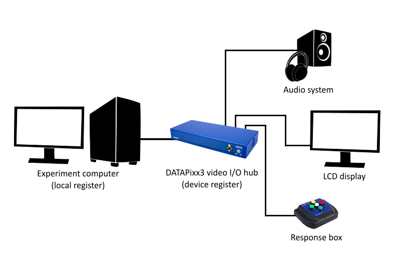
Introduction to Registers and Schedules. Retrieved [Month, Day, Year], from https://vpixx.com/vocal/introduction-to-registers-and-schedules/