This page has been moved to our support documentation website.
See https://docs.vpixx.com/vocal/sending-triggers-with-pixel-mode.
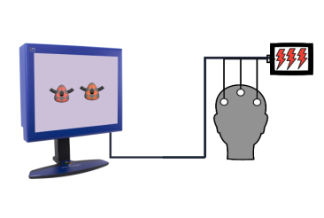
Sending Triggers with Pixel Mode
Use the top leftmost pixel on your display to send custom digital TTL triggers synchronized to frame onset
Contributed by:
Dr. Lindsey Fraser & Dr. Sophie Kenny, VPixx Technologies
Date published:
May 6, 2020